Introduction
Two groups of tolerances are important to know of when talking about mechanical drawings: dimensional tolerances and geometrical tolerances. Dimensional tolerances are the classic group of tolerances that could be specified on a drawing. They are also known as ±tolerances. These tolerances have been around since the 1920s and have basically not changed since then. It was not until the 40s that the geometrical tolerances came about and not until the middle of the 90s that their development really took off.

To specify as well as interpret dimensional and geometrical tolerances on a mechanical drawing, the GPS-system (Geometrical Product Specification) is used, which can be described as a symbolic language for drawings. This language should not be mistaken as the satellite navigation system “Global Positioning System”. About 150 ISO standards collectively define GPS.
Other than GPS, there are other symbolic languages for drawings that are in use out in the world. The largest one among them is the American one, which is defined by the American standard ASME Y14.5. However, GPS is the national standard in the European countries and in many of the other ISO member countries.
In this article, the GPS language is applied and the benefits of using geometrical tolerances versus dimensional tolerances within this language are presented.
Why not only use dimensional tolerances?
Dimensional tolerances are versatile and with them you can specify the tolerance of many different kinds of geometrical features of a part, but not all of its features. How concentric two concentric holes should be relative to each other is one example of this. Moreover, certain applications of these tolerances can be interpreted in more than one way. Below is one example of such an application:

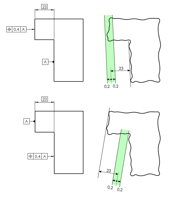
Because there is no default definition among the ISO GPS standards on how this dimensional tolerance shall be interpreted, any possible interpretation is valid (!). A geometric tolerance needs to be specified instead in order to make it unambiguous. For instance a position tolerance. The following illustrations show two methods of how this tolerance could be applied and how they then would be interpreted.

Here you can see how the position tolerance communicates in an unambiguous way. With it, you achieve a consensus about how it shall be interpreted. In the first case where the long side is designated as datum A, the part is within tolerance. In the second case where instead the short side is designated as datum A, the part is outside tolerance.
Closure
In all, the two main features of geometrical tolerances that advocates for why you should use them are:
Complete
Geometrical tolerances supplements dimensional tolerances by enabling the tolerancing of features that otherwise would not have been possible with dimensional tolerances. In theory, you could replace all of the dimensional tolerances on a drawing with geometrical tolerances. Although, this should only be done if it is necessary for the function(s) of the part.
Unambiguous
The design engineer shall be confident that everyone will interpret the drawing the same way. He or she shall not have to shrink the tolerances just because they can be interpreted in different ways. This would make the part unnecessarily expensive. By instead applying geometrical tolerances, this can be avoided. The engineer will in that case be able to maximize the tolerances, which will make the part easier to manufacture and therefore cheaper in return. Also, the risk of placing an order on a part that in the end will not function because the supplier misinterpreted the drawing will be reduced. A situation that could turn out very costly.
Often times, you need to use geometrical tolerances if you want your parts to “measure up”.
About the author:
Daniel Hsiung, Design Engineer
